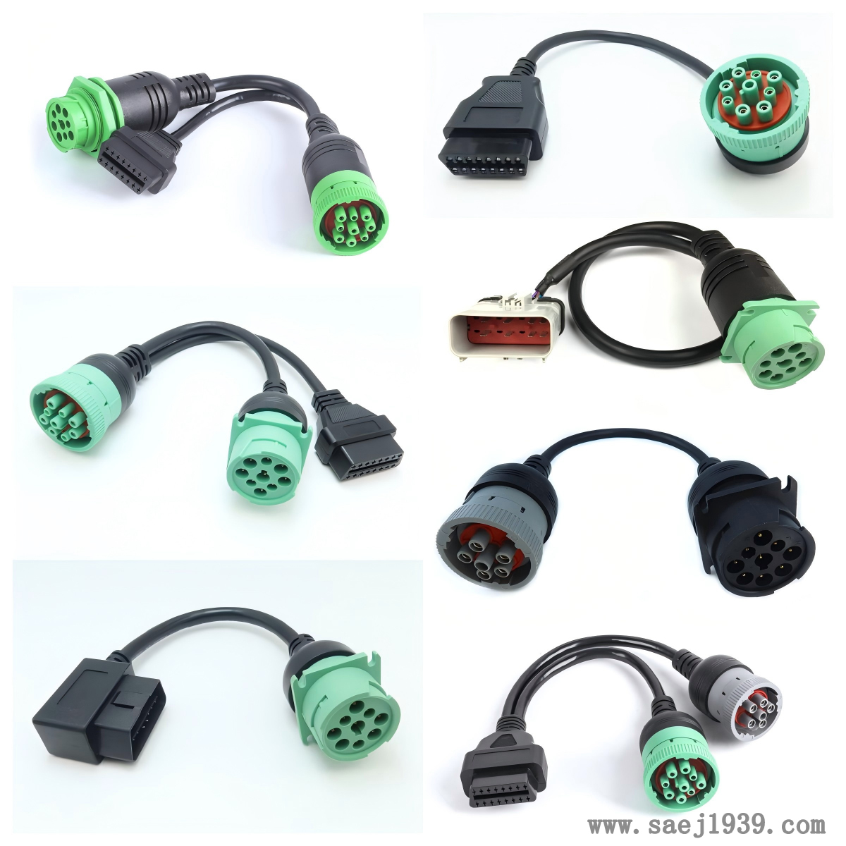
How to test the compatibility of right angle OBD2 to J1939 cable
To test the compatibility of right angle OBD2 to J1939 cables, the following aspects can be taken into account:
Hardware connection check
Ensure that the interface of the right angle OBD2 to J1939 cable matches perfectly with the vehicle's OBD2 interface and the interface of the J1939 devices that need to be connected (such as diagnostic instruments, onboard computers, etc.). Check if the shape, number of pins, and layout of the interface are consistent to ensure correct insertion and good contact, without any looseness or jamming.
Observe the appearance of the cable for any damage, breakage, or short circuit, especially whether the welding at the interface is firm, and whether the cable has wear or peeling. If there are any problems, it may lead to unreliable connections or electrical failures, affecting the compatibility test results.

Electrical characteristic test
Use a multimeter to measure the resistance, capacitance, and other parameters of the cable, and check if they comply with relevant standards and specifications. Different cable lengths and specifications may have different electrical parameter requirements. Generally, the resistance value should be within a certain range to ensure the stability of signal transmission. If the resistance value is too large or too small, it may cause signal attenuation or distortion, affecting communication between devices.
Conduct insulation testing to ensure that the insulation performance of the cable is good and there is no leakage phenomenon. Use an insulation resistance tester to measure the insulation resistance of the cable. The insulation resistance should be high enough to prevent electrical interference and short circuit faults.
Protocol compatibility testing
Using professional diagnostic equipment or testing tools, connect to the vehicle's OBD2 interface and J1939 equipment, and check whether the cable can correctly transmit J1939 protocol signals by sending and receiving specific diagnostic commands and data frames.
Check the support level of J1939 protocol for different vehicle brands and models, as different manufacturers may have some special requirements or extensions for the protocol. Use a variety of representative vehicles for testing, including models from different brands and years, to ensure that the cables are compatible in various practical application scenarios.
Data transmission testing
During the operation of the vehicle, real-time monitoring of data transmission on the J1939 bus is carried out through cables to check for issues such as data loss, errors, or delays. Data loggers or professional bus analysis tools can be used to record and analyze data transmission over a period of time.
Simulate different working conditions, such as vehicle acceleration, deceleration, idle, as well as different environmental temperature, humidity, etc., and conduct data transmission tests again to evaluate the compatibility and stability of the cable under various practical working conditions.
functional testing
Connect various devices that require the use of J1939 protocol, such as electronic control units (ECUs), sensors, actuators, etc., and conduct communication and control function testing between devices through cables.
Test the collaborative working ability between different devices to ensure that when multiple devices are simultaneously connected to the J1939 bus, normal information exchange and functional coordination can be achieved through cables, without conflicts or failures.
When conducting compatibility testing, it is best to refer to relevant industry standards and specifications to ensure the comprehensiveness and accuracy of the testing. If compatibility issues are found with the cable, the cause should be promptly investigated, which may be due to quality problems with the cable itself, mismatched interfaces, incorrect protocol settings, etc. Specific adjustments or replacements should be made for the problem until the test is passed.
We chat